

What Is LoRa? How It Works and Why It’s Ideal for IoT
LoRa is a long-range, low-power wireless technology designed for IoT applications. Learn how LoRa works, how it compares to LoRaWAN, and when to use it for smart sensors, industrial systems, and remote monitoring.
Z-Wave vs Zigbee vs WiFi: Which Smart Home Protocol Is Best?
When building a smart home, choosing between Zigbee, Z-Wave, and WiFi is one of the most important decisions you’ll make. Each wireless protocol serves a different purpose—Z-Wave offers reliable, low-interference communication for security devices, Zigbee excels in large networks of low-power sensors and smart lighting, and WiFi provides high-speed connectivity for cameras and streaming devices. Understanding how these technologies differ helps you create a smart home that is faster, more reliable, and better suited to your automation needs.
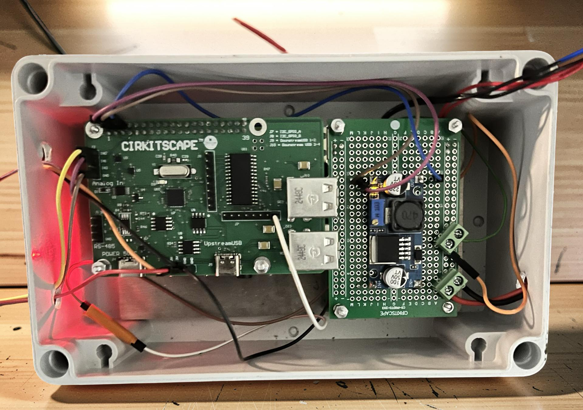
How to Test Raspberry Pi Sensors and Hardware Without Writing Code
The Top HAT Dashboard is a self-hosted Raspberry Pi web interface that lets you test sensors, control outputs, and debug hardware without writing code. Designed for hobbyists and makers, it simplifies hardware testing by providing real-time data, RS-485 communication tools, and a browser-based control panel—all running locally on your Raspberry Pi.

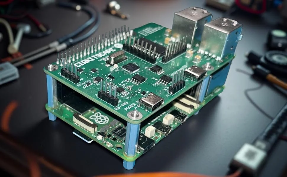
Can Raspberry Pi Power Your Next Industrial Prototype?
For over a decade, the Raspberry Pi has been a favorite tool for hobbyists, students, and makers—powering everything from coding lessons to retro gaming consoles. But in recent years, the Pi has stepped into a new arena: industrial prototyping and edge computing.
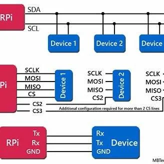
UART vs SPI vs I2C: Which Protocol Should You Actually Use?
If you've ever stared at a microcontroller datasheet wondering whether to use UART, SPI, or I2C for your next project, you're not alone. These three serial communication protocols are the backbone of embedded systems, but choosing the wrong one can lead to headaches down the road.As engineers, we've all been there - debugging a sluggish I2C bus at 3 AM or wondering why our SPI sensor isn't responding. The truth is, each protocol has its sweet spot, and understanding when to use which one can save you countless hours of troubleshooting.
The CHIPS Act Revolution: What It Means for U.S. Electronics Manufacturing in 2025
If you work in electronics manufacturing or hardware development, you’ve probably felt the pain of chip shortages over the last few years. Whether it was waiting months for an MCU, dealing with skyrocketing prices, or scrambling to redesign a PCB around an alternative part, supply chain issues have been a headache for everyone.
That’s where the CHIPS and Science Act comes in. Passed in 2022, this $52.7 billion investment is the U.S. government’s attempt to bring semiconductor production back home, making the industry more resilient and less dependent on overseas fabs.
But what does this mean for engineers, startups, and manufacturers? Is this just another government initiative with no real impact, or will it actually change how we build electronics in the U.S.? Let’s break it down.